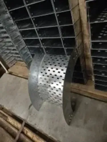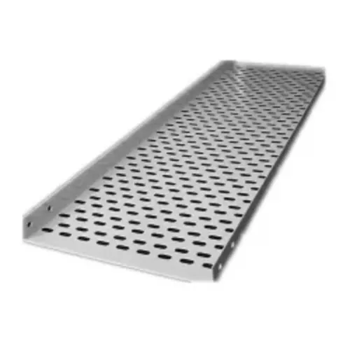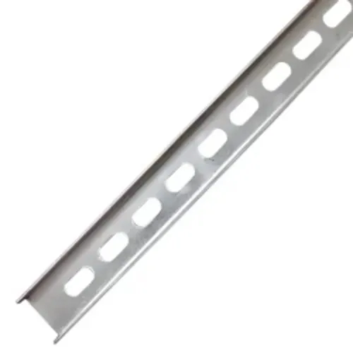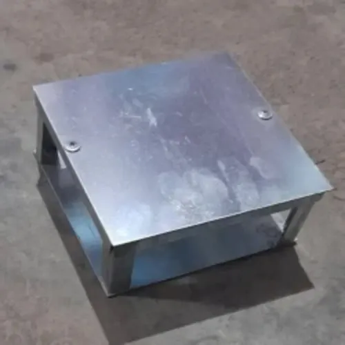
Aluminum reduces the effort and structural demand of installing cable tray, but its lower stiffness means a lighter tray is not automatically a lighter-duty tray. You will be able to compare aluminum with carbon steel, galvanized steel, and stainless steel, verify load and span suitability, and identify the environmental and installation details that determine whether the choice is sound.
Key takeaways
- Choose aluminum when lifting access, support steel, or seismic mass drives the design.
- Verify tray load, support span, deflection, and seismic requirements together.
- Match the alloy and finish to the site’s actual corrosion exposure.
- Check temperature, fire, weather, impact, and thermal movement before installation.
When the weight saving justifies choosing aluminum
At 2.70 g/cm³, aluminum weighs roughly one-third as much as carbon steel at 7.85 g/cm³ for the same metal volume. That advantage justifies aluminum cable tray when crews must carry sections into elevated or congested areas, access is limited, or lower support steel and seismic mass matter more than maximum stiffness.
The saving shrinks when aluminum needs thicker material, a deeper profile, closer supports, or stronger fittings.
| Option | Mechanical trade-off | Best fit |
|---|---|---|
| Aluminum cable tray | Low mass, lower stiffness, and greater sensitivity to denting or deflection | Elevated, access-limited, outdoor, or seismic-mass-sensitive routes |
| Aluminum versus galvanized steel tray | Aluminum is lighter; galvanized steel better resists impact, heavy bundles, and long-span deflection | Choose after comparing the complete rated assembly, not density alone |
| Carbon steel cable tray | Heavier but stiffer and mechanically stronger | Long spans, concentrated loads, severe handling, or impact-prone routes |
| Stainless steel cable tray | Strong corrosion resistance with more mass and cost | Severe chemical, marine, or washdown exposure where strength matters |
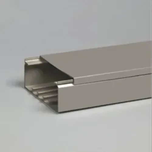
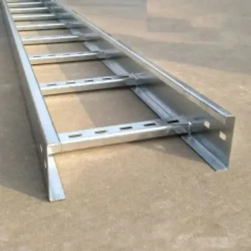
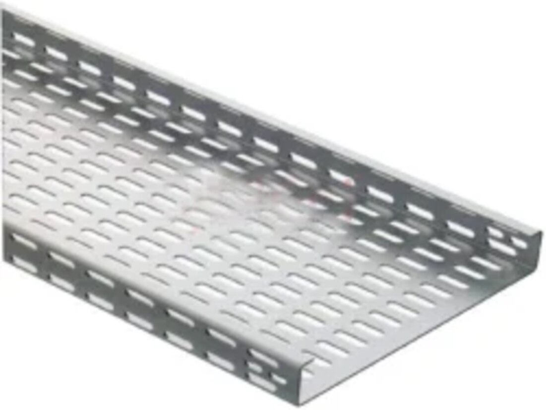
Compare side rails, rungs, covers, splice plates, bends, tees, reducers, and supports. A wide aluminum tray is not automatically adequate for a heavy cable bundle.
Aluminum’s nonmagnetic character avoids ferromagnetic tray behavior near high-current single-conductor circuits, but it does not settle conductor arrangement, induced-current heating, separation, or ampacity. Select a carbon steel cable tray when the aluminum profile cannot control deflection; choose stainless steel when corrosion resistance and strength outweigh low mass.
How to verify load capacity, span, and seismic suitability
Verify the cable tray load rating from the manufacturer’s tested table, not from tray width or aluminum content. The table must match the profile, material thickness, width, rung or perforation pattern, cable tray support spacing, and installation arrangement.
1. Check the table against NEMA VE 1 load and deflection data for the exact tray. Replacing steel with aluminum does not preserve the same allowable span, and a wider tray is not automatically stronger.
2. Add cable weights, tray covers, fittings, future-load allowance, and point loads. Check the heaviest bundle over the longest proposed span against the cable tray span requirements.
3. Review vertical and horizontal bends, tees, reducers, and splice locations. These fittings can change support demands and create concentrated loads.
4. Confirm the specified seismic design, including support bracing, anchor loads, restraint details, and movement at building joints. A tray that passes a static load check can still fail when seismic forces pull supports or anchors sideways.
5. Keep tray strength separate from cable ampacity. NEC 392.80 bases ampacity on conductor type, cable arrangement, tray type, and fill; aluminum material alone does not permit more cable.
6. Reject field drilling, removed side rails, cut rungs, sharp unprotected edges, or improvised splice plates unless the manufacturer’s instructions and design authority approve them. Such changes can reduce capacity, cable protection, or electrical continuity.
Match the aluminum tray to the actual corrosion exposure
Aluminum is practical in ordinary atmospheric exposure, but aluminum cable tray corrosion accelerates when chlorides, chemicals, or trapped water defeat its oxide film.
| Exposure | Suitability | Controls |
|---|---|---|
| Normal air or many outdoor locations | Usually suitable | Provide drainage and inspect damaged surfaces |
| Coastal, marine, or deicing-salt routes | Suitable only with chloride-rated alloy and finish | Use a coastal cable tray design with cleanable surfaces, open drainage, compatible fasteners, and isolation washers |
| Chemical fumes or strong alkalis | Confirm chemical compatibility before approval | Identify the contaminant and specify a resistant alloy, finish, or alternative material |
| Standing water or debris-filled tray | Poor choice until wet conditions are corrected | Eliminate low points, improve drainage, and prevent debris from bridging metals |
Galvanic corrosion occurs when aluminum touches copper conductors, copper fittings, galvanized supports, or stainless hardware while condensation or saltwater provides an electrolyte. Do not assume stainless fasteners solve the problem: exposed-area ratio, coating damage, joint geometry, and the wetting time still control the attack.
Before approval, ask for:
- The tray alloy, surface finish, and environmental limitations
- Fastener material, plating or coating, and the specified isolation washers or sleeves
- A tested jointing method for the exact tray system
- Drainage details, cleaning access, and protection from persistent moisture
- Bonding and compatibility details where copper or dissimilar supports connect
Keep copper away from wet aluminum interfaces, isolate dissimilar metals where specified, and repair damaged coatings. A dry, drained installation can preserve aluminum’s atmospheric advantage; a salt-laden, chemically contaminated, or constantly wet route may justify coated steel or stainless steel instead.
Know where temperature, fire, weather, and impact change the decision
Near furnaces, boilers, process exhausts, or hot roofs, verify the aluminum cable tray temperature limit against the cable’s temperature rating, coating limits, and support details. Aluminum expands more than steel and loses mechanical margin as heat rises, so steel is safer when high temperature and heavy loading occur together.
1. Check the manufacturer’s allowable temperature range, cable rating, coating limit, support spacing, and fitting details. Do not assume a tray rated for ambient service suits a hot process route.
2. Treat fire separately from temperature. Ordinary aluminum tray is not a fire-rated cable tray and will not maintain circuit operation during a fire. Specify a tested fire-resistive assembly covering the tray, supports, cables, mounting arrangement, and fire exposure.
3. For an outdoor aluminum cable tray on a roof or near equipment, verify wind, ultraviolet exposure, drainage, lightning bonding, and access loads. Standing water and salt deposits can turn a corrosion-resistant material into a maintenance problem.
4. Use stronger construction or steel where forklifts, dropped tools, ice, falling objects, or heavy maintenance traffic could dent the tray. Aluminum is practical for many roof-level routes when low mass and atmospheric corrosion resistance matter more than maximum stiffness.
A substation cable tray benefits from aluminum’s nonmagnetic behavior around high-current single-conductor circuits, but ampacity, conductor separation, bonding, and fault-current requirements remain. Check NEC 392.80 and the project design. Do not confuse fire performance with mechanical protection.
Allow for thermal movement and confirm the complete installation
Aluminum moves about 23 × 10⁻⁶ per °C—roughly twice as much as carbon steel. On a long run, calculate movement between the lowest and highest design temperatures before fixing supports or connecting equipment.
1. Calculate the expected movement for the full route, including roof-level temperature exposure and indoor-to-outdoor transitions. Specify an aluminum tray expansion joint or slotted splice connection where the design standard or manufacturer’s instructions require one.
2. Anchor only at designated points and let intermediate supports permit controlled sliding. Do not rigidly restrain every support; preserve fitting clearances and coordinate movement at building joints, walls, and connected equipment.
3. Inspect each horizontal bend, tee, reducer, and vertical transition. A fitting that cannot move with the straight run can bind, distort its splice, or transfer force into supports and equipment.
4. Restore electrical continuity across every discontinuity. Install a cable tray bonding jumper across an expansion joint when the design requires it, and verify that splice resistance, hardware, coatings, and corrosion have not compromised the path.
Under NEC 392.60, confirm the adopted code edition and the conditions for using metallic tray as an equipment-grounding conductor; tray metal alone does not qualify automatically.
For an industrial or infrastructure route, Vickram Engineering can help match tray profiles, fittings, and support arrangements, but require project-specific movement limits, load tables, and written compatibility details. The dependable choice is the complete tested installation, not the lightest raw tray.
Related product
 | Aluminum Cable Raceway By Vickram Engineering Aluminum Cable Raceway from Vickram Engineering is designed to provide a safe, organized, and durable cable management... View product → |
Frequently asked questions
When does aluminum cable tray justify its higher material cost?
Aluminum is practical when low weight reduces handling effort, access equipment, support steel, or seismic mass enough to outweigh its material premium.
How do you verify an aluminum cable tray’s load and seismic suitability?
Check the manufacturer’s load tables for the selected tray width, span, and support spacing, then confirm deflection limits, fittings, covers, and project seismic requirements.
How should you choose aluminum cable tray for corrosive environments?
Identify the actual exposure, including salt spray, chemicals, moisture, and dissimilar metals, then select the alloy, finish, fasteners, and isolation details accordingly.
What conditions can make aluminum cable tray the wrong choice?
High temperatures, fire-rated routes, severe impact, harsh weather, or large thermal movement can require a different material or additional design measures.