A route change on a drawing does not tell you which tray fitting to order. You need to identify the fitting geometry, calculate the cable’s actual bend path, and confirm that the bend matches the straight tray and the surrounding structure. By the end, you will have a practical specification for selecting and checking the fitting before installation.
Key takeaways
- Separate horizontal turns from vertical rises and drops.
- Match bend angle and connection geometry to the straight tray.
- Choose a radius that protects the actual cable bundle.
- Check supports, footprint, and field access before ordering.
Identify the Fitting Type and Route Angle
Trace the route change in plan and elevation before choosing a fitting. A turn left or right in the same horizontal plane requires a horizontal cable tray bend; a rise or drop requires a vertical bend. Measure the included angle from the straight-tray centerlines: common choices are 30°, 45°, 60°, and 90°.
| Fitting type | Route change | Selection clue |
|---|---|---|
| Horizontal bend | Left or right in plan | Use the specified plan angle and orientation |
| Vertical inside bend | Rise or drop toward the inside of the route angle | Match the manufacturer’s inside-bend drawing |
| Vertical outside bend | Rise or drop around the outside of the route angle | Do not substitute an inside bend |
| Tee fitting cable tray | One tray splits into two branches | Use only where the drawing shows a three-way junction |
| Cross fitting | One route divides into three branches | Confirm all four connection directions |
| Reducer | Tray width changes along one route | Specify which side reduces and by how much |
| Offset | Parallel route shifts without a simple single-plane turn | Use the offset dimensions, not a standard bend |
| Field-fabricated corner | No listed fitting matches the geometry | Obtain fabrication details and preserve cable clearance |
Then check the cable path through the fitting, not its advertised outside radius. Select a radius that meets the largest cable’s applicable minimum for pulling and final installation; the most demanding value governs. Rungs, splice plates, and the inside edge can reduce usable clearance.
In a horizontal bend, cables crowd inward, so do not carry straight-tray fill calculations into the turn without checking stacking and separation.
Measure the Tray and Match the Connection Geometry
Before ordering, match the bend to the straight tray in both cross-section and joint layout; a correct 90° fitting is useless if it will not seat or bolt up. Record measurements from the tray drawing, then verify them against a physical sample when the drawing is unavailable.
| Check | What to compare | Why a mismatch fails |
|---|---|---|
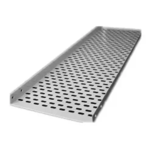
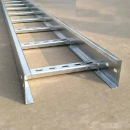
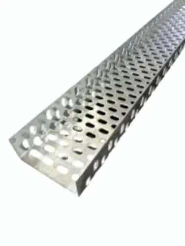
| Tray section | Cable tray width, side-rail height, rung or bottom profile | The bend will not align with the cable-bearing surface |
| Construction | Tray type, material, thickness, and coating | The joint may have different strength, corrosion resistance, or fit |
| Connection | Splice-hole pattern, hole size, plate position, and joining hardware | Splice plates and bolts will not line up |
| Bend geometry | Bend radius at the actual cable path, inside edge, and usable width | A catalogue outside radius can hide a tight obstruction |
Measure the bend’s usable path around rungs, side rails, splice plates, bolt heads, and the inside edge of the fitting. Do not place a splice at the bend throat; an inaccessible joint can obstruct cables and transfer pulling forces into the connection.
Confirm these details before releasing the order:
- Match the straight tray’s hole spacing and orientation, not just its nominal width.
- Check whether the bend uses the same splice plates, bolts, washers, and bonding provisions.
- For a vertical bend, confirm the connection leaves room for the specified cleats, clamps, or tie-downs without reducing the cable path.
Set the Radius for the Actual Cable Installation
The required inside radius is set by the cable with the largest applicable minimum bending radius, not by tray width or nominal bend angle. Check the cable manufacturer’s values for installation, pulling, and final installed positions; use the largest value that matches your method. A bend that works after placement can fail during pulling.
- Cable type: Read the manufacturer’s radius for the specific construction, including single-core, multicore, medium-voltage, or heavily jacketed cable. Do not substitute a generic rule.
- Cable diameter: Use the largest cable diameter in the bundle when checking the cable’s path through the bend. The inside edge, rungs, splice plates, and side rails can reduce the usable radius.
- Cable count: Count every cable entering the bend, then check how the group will spread or stack. A crowded bend increases bend fill and can prevent cables from following the intended radius.
- Pulling conditions: Account for pulling tension, direction, lubrication, pulling speed, and the number of bends. Pulling over a bend creates more strain than leaving the cable in its final position.
- Sidewall pressure: Compare calculated pressure against the cable manufacturer’s limit. Increase the radius, reduce the number of bends, or add a pulling point when the limit is exceeded.
For a sharp route change, a sequence of larger-radius bends can be safer than one tight fitting. Confirm radius at the cable-support surface, not from the catalogue’s outside-radius dimension. Keep the splice outside the cable’s minimum-radius path so hardware does not create a local obstruction.
Check Footprint, Supports, and Field Installation Risks
Approve the bend only after its centreline, tangent length, and support points are plotted on the route drawing. Check cable tray clearance to walls, steelwork, pipework, and adjacent trays; a fitting that matches the tray can still block access or leave no space for pulling.
- Draw the bend at full scale, including the bend centreline radius and tangent length. Confirm that the straight tray reaches both connection points without forcing an offset or moving a support.
- Check the cable’s actual path through the fitting. On ladder tray, rungs, splice plates, side-rail geometry, and the inside edge can reduce usable radius; do not rely on the catalogue’s outside radius.
- Place splices on straight, accessible sections. A splice at the bend throat can obstruct cables, transfer pulling force into the joint, and expose bolt heads to the minimum-radius path.
- Verify support spacing, tray load capacity, and support alignment at the bend. Long pulls need accessible pulling points because a larger radius alone does not eliminate sidewall pressure or excessive tension.
- For vertical bends, specify cleats, clamps, or tie-downs that retain the cables without damaging their jackets or terminations. Do not improvise restraints at the bend.
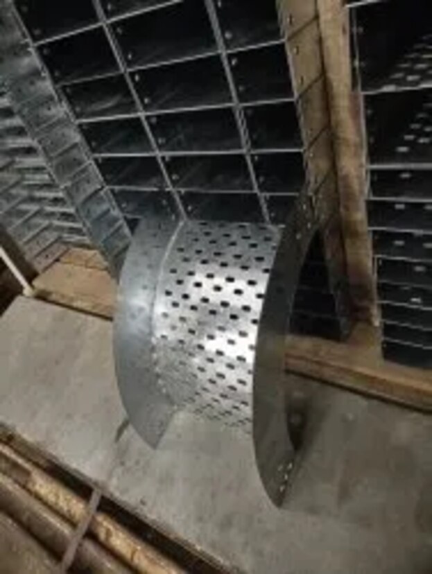
- Compare a factory-made bend versus field-cut bend before approving fabrication. A field cut requires deburring, edge protection, coating repair, accurate splice holes, and bonding continuity.
- Confirm electrical continuity across every joint, including approved bonding jumpers where paint, galvanizing, or a nonconductive coating interrupts metal-to-metal contact.
Turn the Selection into a Complete Bend Specification
A supplier can quote a bend that looks right but cannot be installed if the request omits the joint pattern, support condition, or cable radius. Send one coordinated specification, not only “90-degree bend for 300-mm tray.”
Include these fields:
- Tray type, including ladder, perforated, solid-bottom, or wire-mesh construction.
- Tray width, side-rail height, material and coating, metal thickness, and finish colour if it affects identification.
- Required route angle and fitting orientation: horizontal, vertical inside, or vertical outside.
- Inside bend radius measured along the cable-support path, based on the largest cable’s applicable minimum radius.
- Splice-hole pattern, joining hardware, and the straight-tray section the bend must connect to.
- Required load rating, support span, support locations, and whether the bend is supported at its throat or ends.
- Electrical continuity details, including the bonding jumper arrangement where the joint or coating prevents a reliable fault-current path.
- Cable retention requirements for a vertical bend, such as cleats, clamps, or tie-downs, with cable sizes and spacing.
Attach a marked-up plan and elevation showing the approach direction, exit direction, elevation change, nearby supports, and available footprint. Ask for a dimensioned drawing before fabrication; the drawing must show the inside radius, overall dimensions, hole pattern, and support points.
Whether you send this schedule to Vickram Engineering or another supplier, require the quotation to identify every assumption. Confirm quantity, delivery condition, field-cut allowances, and any accessories separately so an apparently correct bend does not arrive unusable on site.
Related products
Horizontal Cable Tray Bend Vickram Engineering's Horizontal Cable Tray Bend is a precision-engineered cable management accessory designed to facilitate smooth directional... View product → |
 | Fittings Vickram Engineering is a trusted manufacturer and supplier of high-quality cable trays designed for efficient cable management in industrial,... View product → |
Frequently asked questions
How do you identify the correct cable tray bend type?
Trace the route in plan and elevation. Use a horizontal bend for a left or right turn in one plane, and a vertical bend for a rise or drop. Measure the included angle from the straight-tray centerlines; common angles include 30°, 45°, 60°, and 90°.
How do you match a bend to the cable tray?
Measure the tray width, side-rail height, construction, and connection details. Match the bend to the straight section’s dimensions and connection geometry so splice plates, bolts, covers, and fittings align.
How do you choose the correct cable bend radius?
Base the radius on the actual cables being installed, not only the tray size. Check the largest cable’s manufacturer-specified minimum bending radius and allow enough space for the bundle to enter, turn, and leave without forced kinks.
What installation constraints should you check before selecting a bend?
Check the bend’s footprint, available clearance, support locations, access for bolting, cover fit, and nearby equipment. Confirm that the finished route can be supported without loading the bend or obstructing cable installation.