The right cable-support system depends on load, cable geometry, electrical separation, environment and the evidence behind the quotation—not on the label “GI” alone. By the end, you will be able to decide when a ladder tray is the better choice, calculate the information a supplier needs, and compare manufacturers without mistaking a catalogue claim for a tested system.
Key takeaways
- Choose ladder trays for frequent access, ventilation and heavy cable routes.
- Size trays for cable weight, support spans and planned spare capacity.
- Separate cable groups and specify restraint before approving the layout.
- Check coating, damaged areas, testing and every accessory in the quotation.
Use a ladder tray only when its open structure solves the route’s real problem
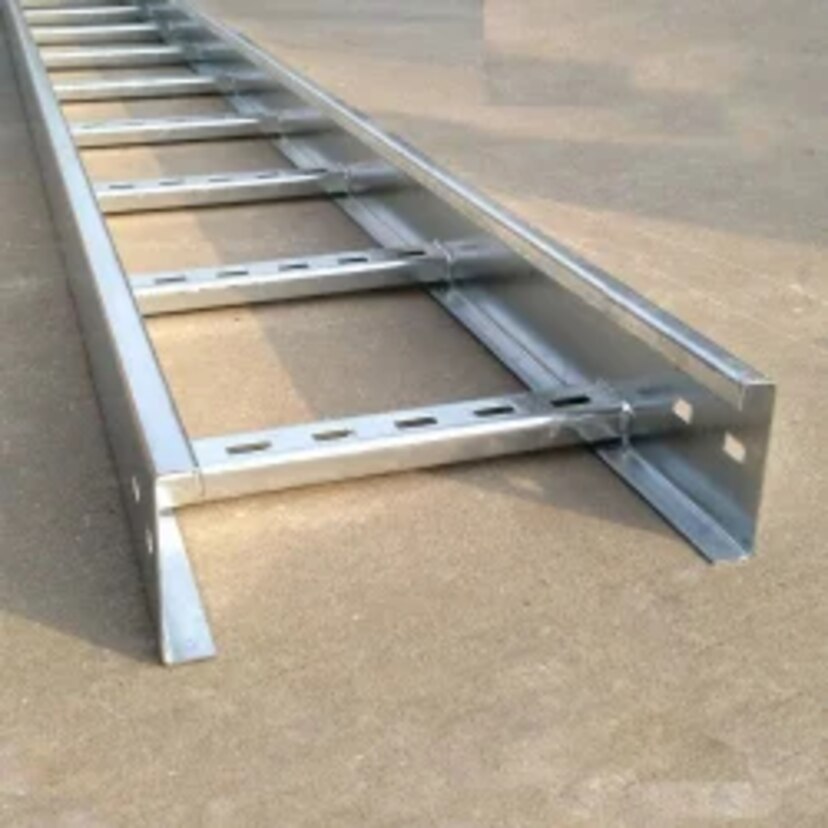
Choose a ladder tray when you need frequent cable access, natural ventilation and a route that can carry heavy cables across supports without enclosing them. The ladder tray decision test is simple: does the open rung structure solve access, heat or weight problems better than a protected enclosed route? If not, choose another system.
| Option | Main advantage | Choose it when |
|---|---|---|
| Ladder tray | Open access and ventilation | Heavy cables need clear support, inspection or easy additions |
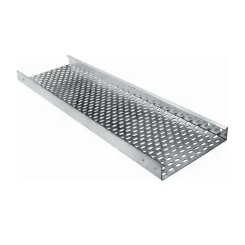
| Perforated cable tray | More continuous support and containment | Smaller cables need a supported base or closer protection |
| Solid-bottom tray | Maximum underside containment | Dust, dripping liquids or small cables could fall through |
| GI raceway with cover | Enclosed, protected route | You need physical shielding and a defined cable enclosure |
| Aluminum raceway | Lightweight, corrosion-resistant enclosure | Weight reduction or a corrosive environment drives the choice |
| Conduit | Strong individual protection | Cables need sealed, mechanically protected runs or separation |
Do not treat open rungs as proof of ampacity; apply the cable manufacturer’s data and the applicable wiring rules for conductor type, grouping, spacing and ambient temperature. Single-core power cables also need cleats or equivalent restraint for prospective short-circuit forces; check IEC 61914 separately from tray capacity.
For the tray, request IEC 61537 or NEMA VE 1 test evidence showing load, span, deflection and configuration. Ask for separate support rules for bends, tees and reducers, because fittings can rate below straight sections.
Size the complete tray system from cable weight to future spare capacity
Calculate the design load before choosing a tray: sum the cable weight per metre across the loaded route, then add the tray, covers, fittings and any specified concentrated loads.
Reserve a defined percentage of both available tray area and load capacity for future cables; spare width alone is useless if the structure is already near its limit.
- Set tray width from cable diameters, required separation, bending radius at entries and the installation clearance needed for pulling or cleating. Do not fill the usable width to its physical edge.
- Select a support span that keeps the calculated load below the manufacturer’s working-load limit at the stated allowable deflection. A shorter span can solve excessive sag, but it adds supports, anchors and installation cost.
- Compare load-versus-span data for the exact tray width, rung spacing, splice arrangement and support type. A thicker side rail does not compensate for a weak splice or widely spaced supports.
- Check tees, crosses, reducers, vertical bends and adjustable splice plates separately. These fittings can require closer supports or carry less load than straight sections.
- Request the test or calculation basis under IEC 61537, or the applicable NEMA VE 1 designation with its full configuration. Do not convert an NEMA label into an IEC rating.
- Treat single-core short-circuit restraint as a separate check. Select cleats under IEC 61914 for prospective fault current, cable arrangement and fault duration; tray capacity does not replace cable restraint.
A quotation that gives only “heavy duty” and one uniformly distributed load is incomplete. Require the allowable deflection, support rules, fitting ratings and a complete bill of materials before approving the route.
Set cable spacing, segregation and restraint before choosing the tray layout
Do not put power, control and single-core cables into the tray as one undifferentiated bundle. Fix the arrangement around ampacity, cable bending radius, heat dissipation and fault restraint before selecting tray width, rung spacing or accessories.
| Cable group | Arrangement in one ladder tray | Main control |
|---|---|---|
| Power multicore | Keep circuits separated from control cables; maintain the specified air gap and avoid blocking ventilation | Limits thermal grouping and EMI |
| Control and instrumentation | Place in a distinct zone, with a divider where required; cross power cables at 90 degrees | Improves power and control cable segregation |
| Single-core AC | Keep each circuit’s phase conductors together in trefoil or the specified flat formation; do not scatter phases across the tray | Controls magnetic effects, heating and fault movement |
| High-fault-current circuits | Secure with IEC 61914 cable cleats at spacing calculated for prospective fault current, cable arrangement and fault duration | Prevents cables jumping out of the tray during a short circuit |
Use the cable manufacturer’s minimum bending radius at every bend, tee and termination. A cable that fits the straight section can still fail when the tray turns sharply or the cleat compresses it.
If power and control cables must share one tray, specify the physical separation, divider height and control-cable screening needed for the signal system. Extra spacing reduces coupling, but it does not replace screened cable, bonding or an EMI assessment.
- phase formation and cleat positions;
- ampacity after grouping and ambient-temperature correction;
- spare space without reducing ventilation or bending clearance.
Match the metal finish to the environment and protect every damaged area
Indoor, dry service can use pre-galvanized steel; coastal, chemical and washdown service require documented corrosion data before you approve a finish. “GI” alone does not identify the substrate, galvanizing route, coating thickness or repair method.
| Environment | Suitable route | Approval check |
|---|---|---|
| Indoor, dry | Pre-galvanized sheet to EN 10346 or ASTM A653 | Confirm coating designation and protect cut edges |
| Outdoor, non-coastal | Hot-dip galvanizing after fabrication to ISO 1461 | Request coating thickness and drainage details |
| Coastal or wastewater | Hot-dip galvanizing, duplex coating or stainless steel | Compare chloride exposure, wetness and expected service life |
| Chemical plant | Hot-dip galvanizing, duplex coating or stainless steel | Obtain compatibility data for the actual acids, alkalis and solvents |
| Washdown or persistent wetness | Duplex coating or stainless steel; use galvanized steel only with evidence | Check cleaning chemicals, splash zones and process temperature |
GI versus pre-galvanized steel matters at welds, drilled holes and cut edges. Hot-dip galvanizing after fabrication generally covers those areas more completely, but hollow sections need properly sized vent and drain holes; trapped chemicals or zinc can cause distortion, hazards and bare areas.
Under ISO 1461, steel at least 6 mm thick requires an 85 µm minimum average coating and 70 µm minimum local coating; thinner steel has lower minimums.
Specify ASTM A780 for repairs after cutting, drilling, welding or handling. The repair procedure must name surface preparation and the approved zinc-rich material. Painting over oily or poorly prepared steel is not a compliant repair.
Audit the manufacturer’s quotation against a tested, complete and installable system
Require a quotation that proves the offered GI ladder tray is a tested, complete and installable system—not a steel thickness and a price per metre. The working load versus span must match your tray width, rung spacing, support type, splice arrangement and allowable deflection.
1. Request the test report or calculation basis to NEMA VE 1 or IEC 61537, naming the standard used, test span, load arrangement, support spacing and deflection limit. Do not convert a NEMA VE 1 designation into an IEC 61537 rating; compare the actual load-versus-span table.
2. Require a dimensional schedule stating steel thickness, rung profile, side-rail height, rung spacing, bend radius and declared tolerances. Confirm that the tolerances preserve accessory interchangeability; mismatched dimensions can force field drilling and invalidate the tested configuration.
3. Demand separate load and support rules for tees, crosses, reducers, vertical bends and adjustable splice plates. Fittings often create rating discontinuities, so a straight-tray capacity cannot cover every route section.
4. Check the bill of materials for splice plates, fittings, covers, supports, fasteners, bonding hardware and any required bonding jumpers. Ask how bolted joints achieve electrical continuity and identify torque, washer and coating requirements; zinc alone does not prove continuity.
For a quotation from Vickram Engineering, use this same schedule to compare the proposed GI ladder tray against competing systems, rather than accepting “heavy-duty” as a rating. Reject any offer that omits support conditions, accessory loads, declared tolerances or the hardware needed to install the route without site modification.
Related product
 | Ladder Type Cable Tray Product Description Vickram Engineering is a leading manufacturer and supplier of premium-quality Ladder Type Cable Trays designed for supporting and... View product → |
Frequently asked questions
When is a GI ladder tray the right choice?
Choose it when frequent cable access, natural ventilation or heavy cables across supports matters more than enclosing and shielding the route.
How do you size a GI ladder tray system?
Check the combined cable weight, support spacing, tray dimensions and planned spare capacity rather than sizing from cable count alone.
What should you decide before selecting the tray layout?
Set cable spacing, segregation between cable groups and the restraint method before choosing tray width, rung arrangement and route details.
What should you check in a manufacturer’s quotation?
Confirm the metal finish, dimensions, load information, testing records, supports, bends, covers, fasteners and other accessories needed for installation.