A GI slotted C channel can support a ladder tray route only when its section, thickness, span, connections and loading are verified together. By checking the tray arrangement, support forces, manufacturer data and Bengaluru exposure conditions, you can decide whether to use a single channel, a reinforced assembly or a different support system.
Key takeaways
- Calculate tray, cable and accessory loads before selecting channel.
- Match trapeze, wall bracket or side support geometry to the route.
- Verify channel capacity, deflection, connections and support spacing together.
- Reinforce the channel when span or combined load exceeds its capacity.
Start with the tray load and support geometry
A GI slotted C channel for ladder tray routes in Bengaluru is suitable only after you establish the route’s load and support geometry. Galvanizing and slots do not provide a rating for a particular tray width, cable mass or span.
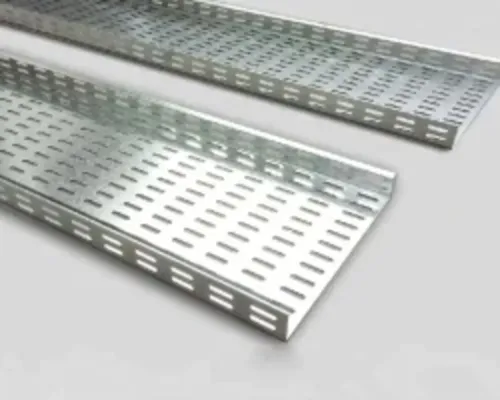
1. Record the ladder tray width, side-rail height, thickness, construction and manufacturer’s tested load table. Note every straight-run length, fitting, reducer, tee, bend and joint location.
2. Calculate the support reaction from tray dead weight, cable weight, covers, separators, accessories, channel or trapeze steel, and future additions. Use cable manufacturer mass data, not conductor size alone. Mark concentrated power-cable loads and drops.
3. Fix the support span from the tray data and joint-support requirements; do not assume a 1.5 m or 2 m spacing rule. Record cantilever lengths and keep supports positioned to control deflection at fittings and joints.
4. Draw the support geometry: trapeze, wall bracket, side support or ceiling drop; channel orientation; threaded-rod locations; and the number of channels at each support. A one-sided tray creates torsion and eccentric loading, so show the load resultant relative to the channel and anchor line.
5. Identify outdoor, rooftop, open-sided or tall-building exposure. Add wind uplift, lateral and seismic actions to gravity load, because these forces can reverse anchor and spring-nut loading.
Check the ladder tray, couplers and supporting steel separately. IEC 61537 evaluates cable ladder and tray systems; it does not certify every GI channel support. The selected channel section, thickness, span and connection arrangement still require structural verification.
Choose the support form: trapeze, side support, wall bracket or drop
The support form determines both the load path and the number of GI channels at each point. A trapeze usually uses one horizontal channel held by two threaded rods, while a wide or heavily loaded route may need two parallel channels or a deeper section.
Galvanizing protects the steel; it does not establish its bending capacity.
| Option | Load and force behaviour | Channel quantity and typical arrangement |
|---|---|---|
| Trapeze | The horizontal channel bends between the rods; eccentric loading adds torsion. | One channel for a centred, verified load; two back-to-back or parallel channels when bending, twist or width exceeds the section’s capacity. |
| Side support | Each side rail transfers load into a separate support, reducing the span of the tray support but demanding accurate level alignment. | Two channels, one beneath each tray side, with tray clamps at both sides. |
| Wall bracket | The channel acts as a cantilever; the wall anchors resist vertical shear and an overturning moment. | One channel for a verified light route; use a deeper section, brace or paired channels for heavy or offset tiers. |
| Drop | Threaded rods carry tension while the cross-channel carries bending; lateral movement can load the rods and nuts. | Two rods and one cross-channel for a stable trapeze; add rods or channels when the route is wide, multi-tiered or exposed to wind. |
For a practical slotted channel tray support, pass two threaded rods through the ceiling, fit washers and spring nuts, and bolt the horizontal channel level. Secure the ladder tray with tray clamps rather than relying on loose contact.
Keep the load near the support’s shear centre; a one-sided multi-tier route twists the channel and increases anchor force.
Treat every channel support for cable routes as a structural assembly, including anchors, rods, nuts and connections—not just the channel. For outdoor Bengaluru routes, check wind uplift and lateral forces before selecting the form.
Check capacity, deflection, connections and support spacing
Verify the complete support assembly against the actual tray load, span and support geometry; galvanizing and slots do not give a channel a default load rating. Use the tray manufacturer’s tested load table, then check the channel section properties and the project’s allowable deflection.
- Calculate cable, tray, cover and future spare-load weight at each support.
- Check channel bending, shear, torsion, local buckling and slot tear-out.
- Check deflection against the project or tray manufacturer’s stated limit; excessive sag can damage joints and reduce cable clearance.
- Verify the number and orientation of channels in the trapeze, side support, wall bracket or drop.
- Check threaded rods, washers, bolts, spring nuts and tray clamps for slip, pull-out and bearing failure.
- Verify anchors into concrete or steelwork for tension, shear and edge distance, including wind uplift and lateral or seismic forces outdoors, on roofs and in tall buildings.
- Confirm that every connection has full fastener engagement, with no damaged slots or thread interference.
Do not apply a generic 1.5 m or 2 m spacing rule. Set straight-run spacing from the tray load table and place supports at tray joints where the tested arrangement requires them. Add supports immediately before and after bends, tees, reducers, risers, drops and direction changes so fittings do not hang from unsupported tray.
Finally, inspect the installed slotted channel tray support for level, straightness, clear cable-pulling paths, service clearance and sharp edges. A sound calculation cannot rescue a twisted channel or a loose anchor.
Know when GI channel is insufficient or needs reinforcement
Use one slotted channel only when its section capacity, connection strength and deflection satisfy the calculated tray load and support span. Galvanizing and slots do not create a load rating. If the channel twists, sags, pulls anchors sideways or leaves the tray joint unsupported, change the support arrangement rather than tightening the spring nuts.
| Option | What it adds | When it applies |
|---|---|---|
| Back-to-back channels | Greater section depth, stiffness and torsional resistance | Use for wide or heavily loaded trays, long spans, or eccentric multi-tier loading. |
| Second reinforcing section | Local bending and slot-bearing resistance | Bolt it beneath or alongside the primary channel where a concentrated drop, separator, tray joint or clamp creates a weak zone. |
| Angle | Lateral restraint or diagonal bracing | Add it when wind, seismic action or one-sided loading can rack a wall bracket or trapeze. |
| Beam | Higher bending capacity over a longer span | Use a structural beam when the required channel size becomes impractical or deflection controls the design. |
| Cantilever bracket | Direct wall-mounted support with a defined arm | Use when rods cannot hang from the slab; check arm bending, wall anchors and torsion. |
| Welded steel frame | A rigid multi-member support | Choose it for several tray tiers, heavy power cables, large offsets or combined vertical and lateral forces. |
For channel support for cable routes, include tray, cables, covers, fittings and future additions in the load. Take cable mass from the manufacturer, then verify the channel, anchors, rods, nuts and tray clamps as one system. Outdoors and on roofs, check uplift and lateral forces; a gravity-only design can reverse anchor forces.
Specify and inspect industrial channel supply in Bengaluru
Do not accept “GI slotted C channel” as a complete specification. For industrial channel supply in Bengaluru, give the supplier the tray width, support span, loaded cable mass, fitting locations and channel arrangement, then request a channel sized as a structural member for that case.
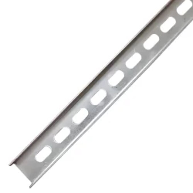
1. Request the channel section size, steel grade, nominal thickness, slot length and width, slot pitch, and whether slots run on the back, flanges or both. Ask for allowable load and deflection at your span, or a test report showing the tested span, loading and failure limit.
2. Specify the coating process and standard. For hot-dip galvanizing, ask whether the coating complies with ISO 1461; for pre-galvanized sheet, request the zinc coating designation and edge-protection method. Require compatible spring nuts, channel nuts, bolts, washers and tray clamps, plus treatment for every cut edge.
3. Check the delivery before installation. Measure thickness and section dimensions, inspect straightness, confirm that slots are not torn or distorted, and reject channels with heavy burrs, bare steel, flaking zinc or blocked slots. Vickram Engineering can be included in the comparison only after its tray and channel interfaces match these measured requirements.
4. Inspect the installed route before pulling cable. Verify support spacing against the tray manufacturer’s load table, support tray joints where required, and check level, rod engagement, washer placement, nut seating and anchor installation. Confirm clearance for cable pulling and remove sharp edges that could cut sheaths.
5. For outdoor, rooftop, open-sided or tall-building routes, obtain wind and seismic design forces; gravity-only sizing can leave anchors vulnerable to uplift or lateral reversal.
Frequently asked questions
What must you calculate before choosing a slotted channel tray support?
Calculate the combined weight of the ladder tray, cables, covers, fittings and future additions over the proposed support spacing. Then define the span, support direction, connection points and clearances before selecting the channel section.
Which support form suits a ladder tray route?
Use a trapeze for a suspended tray, a side support when the tray attaches beside a structure, a wall bracket for a wall-mounted route, and a drop arrangement when the tray hangs below a slab or steel member. Select the form that keeps the load centred over its connections.
How do you check a channel support for a cable route?
Check the channel manufacturer's capacity table for the proposed span and loading, then verify deflection, bolt or nut connections, anchor strength and support spacing. Inspect the complete assembly rather than treating the galvanized channel alone as the rating.
When is GI slotted C channel insufficient for a ladder tray?
Replace or reinforce it when the calculated load, span or deflection exceeds the channel's published limits, or when connections and anchors cannot transfer the load. Add a second channel, reduce spacing, shorten the span or use a heavier structural section.
What should you request from an industrial channel supplier in Bengaluru?
Request the channel size, steel thickness, galvanizing specification, section properties, load tables, slot dimensions, connection hardware and batch or inspection records. Compare those documents with the approved tray layout and the project's support calculations.
Keywords