A damaged or overcrowded ladder tray does not regain maintainability simply because a new section is installed. You need to identify the existing circuits, create a controlled transfer path, match the replacement to the actual span and load, and leave enough clearance for the next inspection or cable addition.
Key takeaways
- Measure tray width, side-rail height, rung spacing, and support locations before ordering.
- Use aluminum sections when lifting, carrying, and positioning replacement tray is the main site constraint.
- Transfer cables in identified groups and preserve spare room for future maintenance.
- Compare load capacity, corrosion exposure, fittings, bonding, and installation effort—not weight alone.
What restoring ladder-tray cable access means on site
Restoring ladder-tray cable access means reopening a congested route, replacing damaged sections, creating a reachable maintenance path, or recovering working room after cable additions. Open rungs let technicians lift, inspect, identify, and re-lay cables without pulling every circuit through an enclosed raceway.
That benefit disappears when pipework, ductwork, adjacent trays, or permanent covers block working clearance. Aluminum cable tray cable routing improves visibility only when technicians can reach the cables, splice points, and supports.
Use this recovery sequence:
- Isolate circuits, confirm circuit identity, photograph the existing layout, and attach durable labels to every cable.
- Survey cable count, cable diameter, tray fill, spare capacity, and circuit separation. Keep power, control, instrumentation, and communications cables separated where the code or project specification requires it.
- Inspect for missing rungs, distorted rails, rusted joints, failed splice plates, overloaded spans, inaccessible supports, sharp edges, and cables resting on nearby steelwork.
- Decide whether the damage requires whole-run replacement or only damaged ladder sections, selected bends, or splice points.
- Temporarily support cables, separate them by circuit, and transfer them in stages. A new tray does not restore aluminum cable tray ladder tray access if an unidentified bundle is simply dropped into it.
- Deburr field cuts, protect cable jackets, preserve bend radius, install approved splice and bonding hardware, and verify that covers remain removable where access matters.
Before energising, test circuit identity, continuity, insulation resistance, and bonding continuity, then update route drawings.
Why aluminum reduces the handling burden during recovery
At about 2.70 g/cm³, aluminum weighs far less than ordinary steel at approximately 7.85 g/cm³. That difference reduces the handling burden when technicians lift replacement sections above equipment, through congested plant rooms, or where crane and forklift access is restricted.
The aluminum cable tray recovery benefits appear during sectional removal and refitting, not only during initial routing.
| Option | Weight and handling | Exposure and performance |
|---|---|---|
| Aluminum | Lightest; easier to position | Protective oxide film, but inspect for wetting, standing water, dust, washdown, and contaminants |
| Galvanized or mild steel | Heavier; greater lifting effort | Higher impact resistance and rigidity; coating damage can expose steel |
| Stainless steel | Heaviest and costly to handle | Strong corrosion resistance; use where the specification demands it |
Before selecting a replacement for aluminum cable tray ladder tray cable for access in Bengaluru, check these disqualifiers:
- Reject aluminum where forklifts, falling objects, exceptional rigidity, fire protection, electromagnetic control, chemical resistance, or a steel specification governs the route.
- Confirm the support span, allowable load, fire requirements, bonding method, and compatibility with existing brackets; lower dead weight does not permit wider spans.
- Provide expansion joints or movement provisions on long runs, and use bonding jumpers that preserve continuity after thermal movement.
- Separate aluminum from carbon steel or copper in wet, contaminated locations with compatible connectors, isolating washers, suitable coatings, or approved fasteners. Otherwise galvanic corrosion can attack the joint.
- Deburr field cuts and retain the manufacturer’s approved splice arrangement; an improvised overlap can damage cable jackets and break bonding continuity.
A removable cover can address falling objects, UV, or washdown, but a permanently bolted cover defeats the access recovery purpose.
How to verify structural fit before ordering replacement sections
A replacement fits only when it matches the route, support arrangement, cable load, and maintenance space—not merely the rail profile, metal thickness, or appearance. Calculate cable weight per metre, concentrated loads, support spacing, expected deflection, cantilever limits, and working clearance before selecting aluminum cable tray cable routing.
Use the manufacturer’s tested load-versus-span table for the planned span. NEMA VE 1 load classes of 50, 75, 100, 125, and 150 lb/ft have meaning only with their specified support span.
Evidence to verify includes:
- Tray width, side-rail height, rung spacing, splice geometry, cover or divider arrangement, and bonding method.
- Beams, pipework, sprinkler clearances, access doors, lifting restrictions, and space for split sections or staged removal in the Bengaluru plant room.
- Cable separation, fill, earthing, and fire provisions confirmed by the engineer of record against the adopted design standard and local electrical requirements.
| Check | Accept only when | Reject when |
|---|---|---|
| Manufacturer table | The rating covers the planned span and calculated load | The supplier gives only width or thickness |
| Existing route | Dimensions and splice geometry match | Sections require improvised drilling |
| Working space | Cables can be lifted and inspected | Pipework or adjacent trays block access |
| Long run | Thermal movement provisions and bonding jumpers are detailed | Expansion could break continuity |
This verification protects aluminum cable tray ladder access after installation. Long runs need movement provisions because aluminum expands more than steel, while bonding jumpers must preserve continuity across moving joints.
How to transfer cables without losing future maintenance access
Plan the transfer as a circuit-by-circuit recovery, not as a move of one unidentified bundle. That sequence preserves aluminum cable tray recovery benefits and keeps aluminum cable tray ladder tray access usable after the work is complete.
1. Coordinate the shutdown, permits, access equipment, lifting method, cleaning, retesting, and contingency time. Isolate each circuit, verify absence of voltage, photograph its route, and attach durable labels at both ends.
2. Support and displace cables in stages with temporary slings, rollers, or approved supports. Never walk on the tray or use it as a cable-pulling surface; controlled lifting protects jackets and installers.
3. Inspect brackets, spans, bends, rungs, rails, and existing joints for distortion, overload, failed splice plates, inaccessible supports, rust, sharp edges, and cables resting on adjacent steelwork.
4. Fit the replacement section with approved splice plates, fasteners, and bonding provisions. Deburr every field cut, remove swarf, and install edge protection where a cable crosses a transition.
5. Refit each circuit separately, controlling minimum bend radius and maintaining specified separation between power, control, instrumentation, and communications cables. Leave spare width, visible labels, supported bends, and reachable splice locations.
6. Before energising, test continuity, insulation resistance, bonding continuity, and circuit identity. Record the results, update route drawings and as-built records, and correct any failed retest before release.
Removable covers can shield cables from UV, washdown, falling objects, and impact. A permanently bolted solid cover can erase the maintenance access the ladder tray was installed to recover.
What to compare before choosing an aluminum recovery system
Ask for comparable documents, not a metal-thickness claim. For an aluminum cable tray, ladder tray, and cable access project in Bengaluru, request:
- Alloy and temper, tray width and side-rail height, rung spacing, and mass per metre.
- Tested load-versus-span table, planned support spacing, allowable deflection limit, and concentrated-load rating.
- Splice-plate geometry, fastener grade, torque instructions, field-cut and deburring method.
- Surface finish, corrosion limitations, installation instructions, approved bonding-continuity method, and inspection or test records.
| Option | Useful when | Check before selecting |
|---|---|---|
| Aluminum replacement section | A damaged or congested straight run needs sectional recovery | Dimensions, load, movement provisions, and galvanic isolation |
| GI ladder tray | Impact resistance, rigidity, or existing steel compatibility governs | Corrosion condition, dead load, and joint continuity |
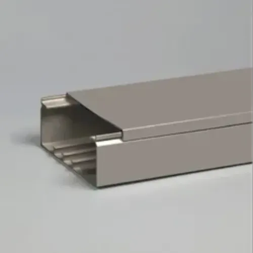
| Aluminum raceway | Exposure, segregation, washdown, or falling-object protection justifies enclosure | Removable access, heat dissipation, cable fill, and cover fastening |
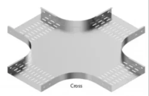
| Horizontal bend or GI bend | Damage is limited to a direction change | Bend radius, cable support, splice fit, and adjacent clearance |
Open ladder construction is preferable for visible tracing, additions, and future sectional replacement. Choose a raceway or cover only when exposure or segregation needs outweigh access; a bend or splice repair is wasteful when the straight run remains sound.
Record route condition, supports, cable identity, spare capacity, access constraints, isolation method, and final test results. Vickram Engineering can be compared with other suppliers after the site survey confirms these details and the replacement sequence. This is how aluminum cable tray recovery benefits become measurable rather than another inaccessible bundle.
Related products
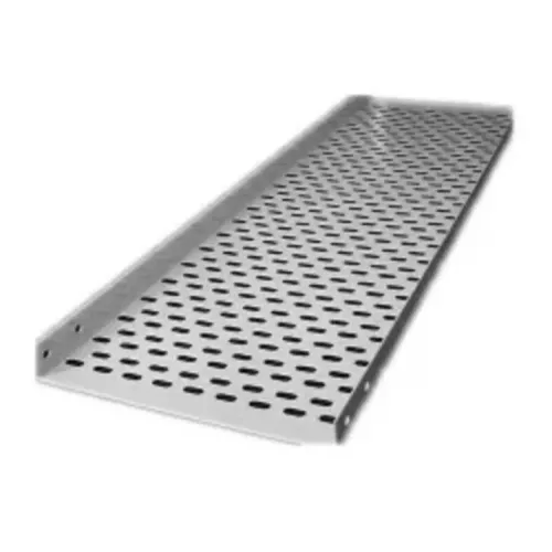
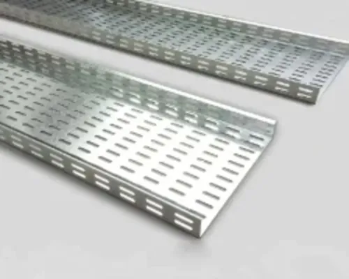
 | Ladder Type Cable Tray Product Description Vickram Engineering is a leading manufacturer and supplier of premium-quality Ladder Type Cable Trays designed for supporting and... View product → |
Horizontal Cable Tray Bend Vickram Engineering's Horizontal Cable Tray Bend is a precision-engineered cable management accessory designed to facilitate smooth directional... View product → |
Frequently asked questions
What does restoring ladder-tray cable access mean on site?
It means reopening a congested route, replacing damaged sections, creating a reachable maintenance path, or recovering working room after cable additions.
Why does aluminum reduce the handling burden during recovery?
Aluminum reduces the weight technicians must lift, carry, and position when replacing or extending ladder-tray sections, which can simplify work in restricted areas.
How do you verify structural fit before ordering replacement sections?
Check tray width, side-rail height, rung spacing, section length, support spacing, joint details, cable load, clearances, and the existing system’s fittings.
How can you transfer cables without losing future maintenance access?
Identify and support cables in manageable groups, maintain separation and bend-radius requirements, avoid overfilling the tray, and leave reachable working room around the route.
What should you compare before choosing an aluminum recovery system?
Compare load capacity, alloy and finish, corrosion exposure, tray dimensions, fittings, bonding continuity, support requirements, installation effort, and lifecycle maintenance access.
Related products
 | Aluminum Cable Raceway By Vickram Engineering Aluminum Cable Raceway from Vickram Engineering is designed to provide a safe, organized, and durable cable management... View product → |
 | Galvanized Cable Tray Vickram Engineering's Galvanized Cable Tray is engineered to provide a strong, reliable, and corrosion-resistant cable support system for industrial,... View product → |
Cable Trays The GI Bolt Nut Type Cable Tray is a robust and dependable cable management solution designed for safe routing and support of electrical,... View product → |
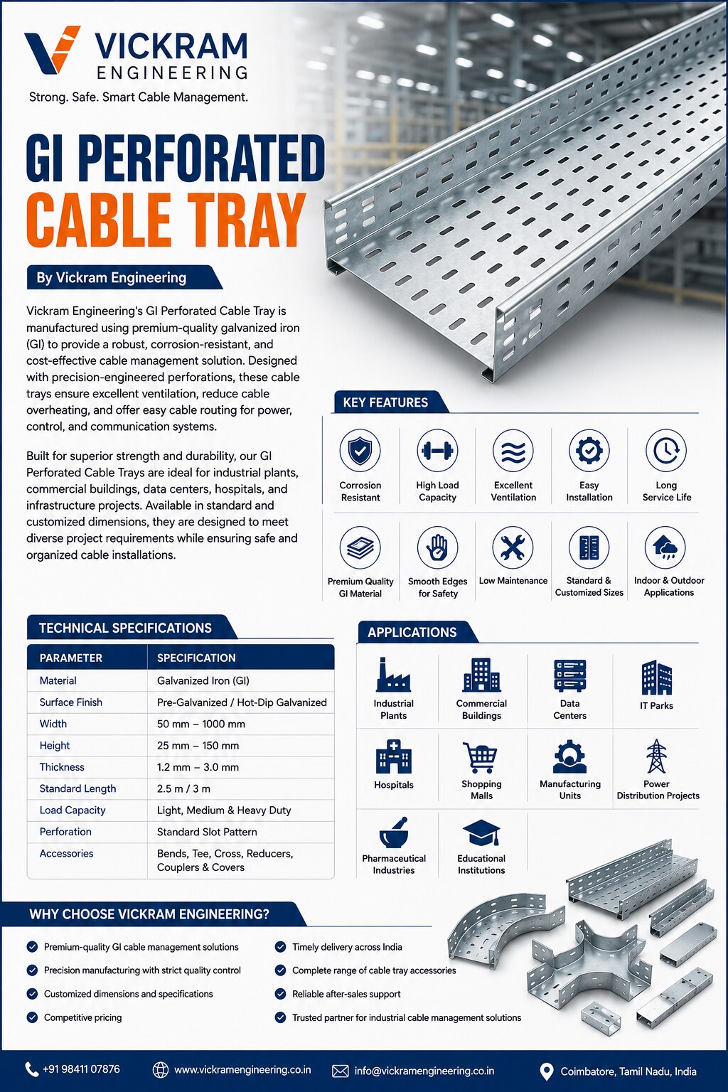 | GI Perforated Cable Tray Vickram Engineering's GI Perforated Cable Tray is manufactured using premium-quality galvanized iron (GI) to provide a robust, corrosion-resistant,... View product → |
Keywords