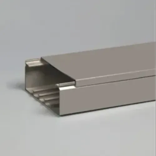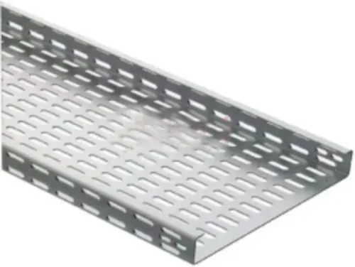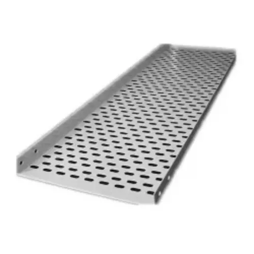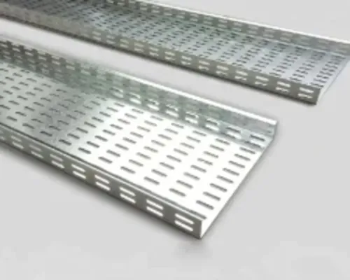
A plant route can fail at a bend even when the straight tray is correctly sized: the angle, radius, orientation, coating, support, and splice pattern all affect cable installation. By the end, you will be able to match each route change to the right fitting, specify a compatible bend family, and check the delivery before installation.
Key takeaways
- Match horizontal, vertical inside, and vertical outside bends to route geometry.
- Set bend radius from the largest cable’s minimum bending radius.
- Compare GI, stainless steel, aluminium, and painted steel against site conditions.
- Demand a bend schedule, fit check, support plan, and complete supplier deliverables.
Match the Fitting to the Route Geometry
A horizontal bend changes the route in plan; a vertical inside bend turns the tray upward or downward on the inside of its curve, while a vertical outside bend turns it on the outside. They are not interchangeable because the cable-support surface and retention points change.
The search phrase cable tray bend for options manufacturing plants in Bengaluru is useful only after this geometry is identified.
| Fitting | Route geometry | Use |
|---|---|---|
| Horizontal bend | Left or right plan change | Shift around machines, columns, or walls |
| Vertical inside bend | Upward or downward turn on the inside radius | Rise or drop while keeping the cable supported inside the curve |
| Vertical outside bend | Upward or downward turn on the outside radius | Clear an obstruction where the outer curve controls the route |
| Tee | One route divides into two | Feed a machine line from a main tray |
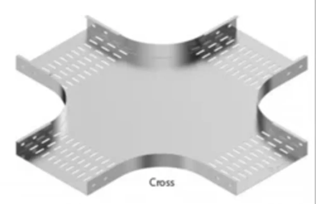
| Cross | One route divides into three | Interconnect four tray runs |
| Reducer | Tray width changes | Match a narrower branch without abrupt cable contact |
| Field-fabricated mitre | Sections cut and joined on site | Use only with approved drawings; poor cuts create sharp edges and weak joints |
For a cable tray bend comparison, treat 30° as a gentle offset, 45° as a practical gradual turn, 60° as a tighter change, and 90° as the shortest direct corner. Two 45° bends can reduce pulling force in a congested route; a large-radius 90° bend protects cables but occupies more space.
Measure the largest cable diameter, apply that cable maker’s minimum bending radius, and compare it with the tray’s inside radius. Select the larger requirement, then check covers, dividers, splices, supports, vibration, and movement at building or equipment joints.
Choose the Angle and Radius from the Cable, Not the Tray Alone
Select the fitting radius from the cable with the greatest published minimum bending radius, then confirm that the tray’s usable inside radius meets or exceeds it through the entire curve. The largest, stiffest cable—especially MV, XLPE, armoured, or heavily screened cable—usually governs.
Use the cable manufacturer’s installation radius, not only its final installed radius. Also obtain the allowable pulling tension and sidewall pressure; a tight curve can damage insulation even when the cable appears to fit.
| Angle | Route effect | Selection guide |
|---|---|---|
| 30° | Small direction change | Use where the route can turn gradually with minimal space |
| 45° | Moderate direction change | Use two fittings when a single 90° bend would create high pulling force |
| 60° | Strong direction change | Use when the route needs more turn but space remains limited |
| 90° | Complete direction change | Select a large-radius fitting, not the smallest standard elbow |
A cable tray bend comparison must separate horizontal bends from vertical inside and vertical outside bends. Horizontal fittings change the plan direction; vertical fittings change elevation, and their support surfaces and retention geometry are not interchangeable.
For industrial cable route bends in Bengaluru, check the route at building joints, machine foundations, pipe racks, and separate structures. Provide an expansion joint or flexible detail where movement or vibration could transfer through a rigid bend and splice.
Maintain segregation through the bend. A divider that stops before the curve, or a radius that suits power cable but not instrumentation cable, defeats separation and can force field rework.
Compare GI, Galvanized, Stainless, Aluminium, and Painted Steel
Material choice follows the route environment, not Bengaluru’s inland location alone. A dry indoor production line needs less protection than a rooftop route exposed to monsoon rain, cooling-tower moisture, process dust, or chemical fumes.
| Material and finish | Best fit | Check before approval |
|---|---|---|
| GI, pre-galvanized steel | Dry indoor manufacturing routes | Confirm coating on cut edges, holes, welds, and splice plates |
| Hot-dip galvanized steel | Wet areas, service corridors, and many outdoor routes | Specify hot-dip galvanizing after fabrication and the required zinc repair method |
| Stainless steel, preferably 316 where chemicals or chlorides are present | Washdown rooms, corrosive process zones, and aggressive chemical exposure | Confirm chemical compatibility; stainless is not immune to every cleaning agent |
| Aluminium | Rooftops or routes where low weight and corrosion resistance matter | Isolate it from dissimilar metals to prevent galvanic corrosion |
| Painted steel | Dry indoor areas or a specified colour-coded system | Require surface preparation, coating thickness, and touch-up instructions; damaged paint exposes steel quickly |
Do not write “GI” as the complete purchase description. A GI bend for manufacturing plants could mean pre-galvanized steel or hot-dip galvanized steel after fabrication, and those systems protect drilled holes, welds, and cut edges differently.
For washdown, inspect fasteners and splice hardware as carefully as the bend. Chlorinated cleaners, fertilizer dust, acids, and alkalis can attack a finish that performs well in ordinary rain.
A rooftop bend also needs sealed or repaired penetrations and a coating suited to continuous weather exposure. Use painted steel only when the paint system is specified, not as a cheaper substitute for corrosion protection.
Read the Bend Schedule and Complete a Fit Check Before Ordering
A bend connects correctly only when its tray profile, connection pattern, radius, and elevation match the straight sections at both ends. For cable tray bend options for manufacturing plants in Bengaluru, complete the fit check against the latest route drawing, not a supplier catalogue sketch.
1. Confirm the nominal tray width and side-rail height, then verify the clear inside width after dividers, covers, and joint plates are fitted. Record the straight tray’s side-rail profile and material finish.
2. Check the bend angle, horizontal or vertical orientation, inside radius, outside radius, tangent lengths, and finished elevation. A 90° horizontal bend and a 90° vertical inside bend are not interchangeable.
3. Overlay the bend on the route drawing and mark the entry and exit centre lines, direction of travel, handedness, and available clearance from columns, machines, pipes, and walls. State dimensions to fixed gridlines or equipment faces.
4. Match the bolt-hole pattern, splice-plate type, fastener size, cover arrangement, divider height, and divider continuation through the bend. A divider that stops at the straight tray leaves segregation gaps for power, control, instrumentation, or communication cables.
5. Verify the bend’s support points separately. Show support locations near the bend and tangent points, plus load capacity and pulling-load assumptions; a straight-run span table does not validate an unsupported fitting.
6. Include the drawing number and revision, quantity, packing condition, expansion-joint or flexible detail, and every required accessory. This prevents a cable tray bend for options manufacturing plants in Bengaluru from arriving with missing hardware or an unbuildable joint.
Specify Supports, Segregation, and Supplier Deliverables
Require a complete bend-family package before approval, not a price for one fitting. A cable tray fittings supplier in Bengaluru must show how each bend connects, carries, separates, and moves with the plant route.
1. Submit dimensioned drawings for horizontal, vertical inside, and vertical outside bends, including angle, centreline radius, tray width, side-rail height, usable cable width, and bolt-hole pattern. Mark the largest cable diameter and minimum bending radius used to select each fitting.
2. Provide a compatibility schedule covering straight tray, ladder, tee, cross, reducer, cover, divider, splice plate, and support system. Reject the family if it needs site cutting, has mismatched hole patterns, or creates an abrupt cable-contact edge.
3. State the support arrangement: maximum support spacing, support type, allowable load per metre, bend load assumptions, splice location, and fastener grade and finish. Include extra support requirements near bends, tees, equipment entries, and tray ends.
4. Show segregation details for power, control, instrumentation, and communication cables. Identify divider height, divider fixing method, cover clearance, and whether separate compartments continue through every bend.
5. For industrial cable route bends in Bengaluru, document expansion joints, vibration, machine movement, and transitions between structures. Specify expansion splice plates or flexible details where a rigid joint could transfer movement into the tray or cable.
6. State material, coating, inspection records, packing, and delivery condition. For a GI bend for manufacturing plants, include coating specification and touch-up method. Vickram Engineering can be asked to issue this bend schedule as a controlled approval drawing rather than leaving dimensions to site interpretation.
Related products
Horizontal Cable Tray Bend Vickram Engineering's Horizontal Cable Tray Bend is a precision-engineered cable management accessory designed to facilitate smooth directional... View product → |
 | Fittings Vickram Engineering is a trusted manufacturer and supplier of high-quality cable trays designed for efficient cable management in industrial,... View product → |
Frequently asked questions
How do you match a cable tray bend to the route geometry?
Use horizontal bends for changes in plan, vertical inside bends for upward or downward turns inside the curve, and vertical outside bends for turns on the curve’s outside. These fittings are not interchangeable because the cable-support surface and retention points differ.
How should you choose a cable tray bend angle and radius?
Choose the angle from the route drawing and set the radius from the largest cable’s minimum bending radius, rather than selecting a bend from tray dimensions alone.
Which cable tray bend material suits a manufacturing plant?
Compare GI, galvanized steel, stainless steel, aluminium, and painted steel against corrosion exposure, mechanical loading, temperature, weight, grounding requirements, and maintenance conditions.
What should you check before ordering cable tray bends?
Review the bend schedule, verify dimensions and orientation against the route, complete a physical or drawing-based fit check, and confirm supports, segregation, and supplier deliverables.
Keywords