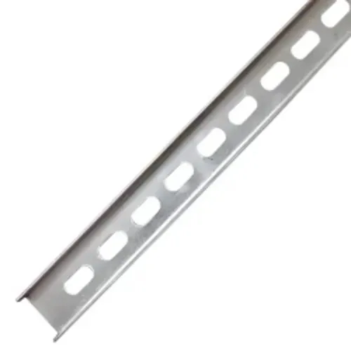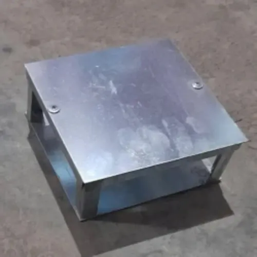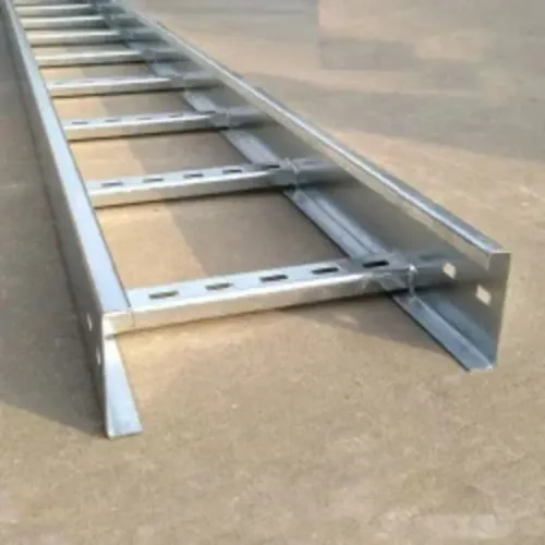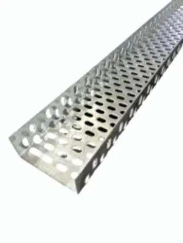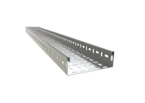
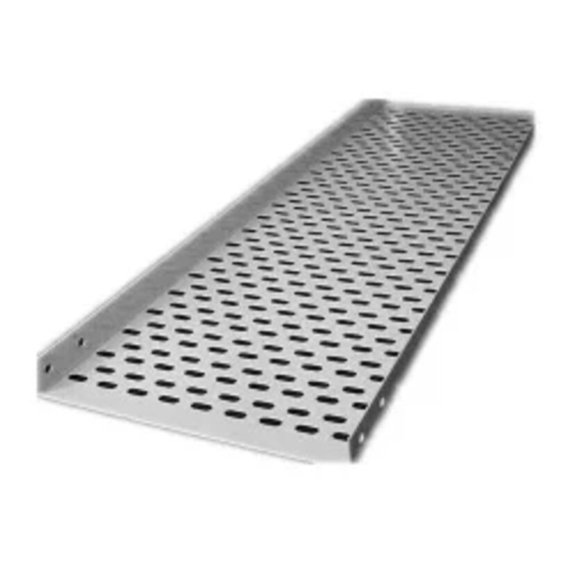
A galvanized tray is not automatically suitable because it carries the word “galvanized” in its specification. You need to match the coating route, environment, cable load, separation requirements, support design, and bonding method to the installation before you place an order.
Key takeaways
- Match the galvanizing method and tray material to moisture, chemicals, and temperature.
- Size trays for cable fill, heat dissipation, separation, and future additions.
- Bond tray sections and verify continuity across joints, fittings, and supports.
- Specify coating thickness, steel grade, dimensions, testing, and repair requirements.
How zinc protects the steel—and why the galvanizing route matters
Zinc protects steel in two ways: the zinc coating forms a barrier against moisture and oxygen, while sacrificial protection protects small exposed areas. If a scratch or cut edge reaches the steel, nearby zinc corrodes first and supplies electrochemical protection; the zinc is consumed, so large damaged areas and repeated abrasion still need repair.
White rust, the powdery zinc-corrosion product caused by wet, tightly stacked storage, can also consume the coating. Store trays dry, separated, and ventilated.
| Option | What the process means | When it applies |
|---|---|---|
| Pre-galvanized sheet | Zinc coating is applied to sheet before the tray is formed; cuts, holes, and formed edges can expose steel | Dry indoor areas or controlled environments where fabrication damage is limited |
| Electro-galvanized steel | Zinc is deposited electrically, producing a thin, smooth coating | Clean, dry interiors where appearance and light corrosion resistance matter |
| Hot-dip galvanized steel | The completed tray is immersed in molten zinc, coating fabricated surfaces, welds, and exposed edges | Outdoor, humid, industrial, or maintenance-critical installations |
Specify hot-dip galvanizing after fabrication when the tray will face rain, condensation, process moisture, or difficult access for repair. Request ASTM A123/A123M or ISO 1461 compliance, with the coating class and minimum thickness or mass stated for the steel thickness.
After drilling, cutting, welding, or grinding, repair exposed steel with the specified zinc-rich coating procedure; “galvanized” alone is not a complete purchase specification.
Choose the coating and tray material for the actual environment
Choose hot-dip galvanized steel when you need high mechanical strength, outdoor durability, routine inspection, and straightforward bonding without the maintenance burden of paint. It is a strong default for dry buildings, humid plant areas, warehouses, and general outdoor routes.
| Option | Main advantage | When it is the better choice |
|---|---|---|
| Hot-dip galvanized steel | Strong, repairable, and protected by sacrificial zinc | Industrial loads, outdoor exposure, humid areas, and projects needing metal continuity |
| Aluminium | Light and naturally corrosion-resistant | Weight-sensitive installations or locations where steel handling is difficult; it carries less load for the same section |
| Stainless steel | Highest resistance to severe corrosion | Coastal air, salt spray, wastewater, and chemical plants where chlorides, acids, or cleaning chemicals would rapidly consume zinc |
| Painted mild steel | Lower initial material cost and colour control | Dry indoor rooms; scratches and cut edges need immediate paint repair or rust will spread |
| Fiberglass-reinforced plastic | Nonconductive and resistant to many chemicals | Electrically isolated routes, corrosive process areas, or sites where low weight matters more than metal strength and bonding |
Galvanized steel is not automatically the cheapest over its service life. Severe marine or chemical exposure can consume zinc quickly, making stainless steel or FRP the better investment; confirm the actual chemicals, concentration, temperature, and splash frequency.
Treat white rust as a storage warning, not proof of immediate failure. Keep trays dry, separated, and ventilated. After cutting or drilling, repair exposed steel with the specified zinc-rich coating; repeated abrasion or large damaged areas need more than the surrounding zinc can provide.
Size the tray around cable load, heat, separation, and future capacity
Start with the cable schedule, not a standard tray width. Record each cable’s outside diameter, cable weight per metre, minimum bend radius, ampacity, voltage class, and required separation; then reserve capacity for the next expansion.
1. Set the width by drawing the actual cable arrangement. Add cable diameters, specified gaps between power cables and control or instrumentation circuits, and the planned spare allowance. Confirm that the resulting load fits the tray’s usable fill area rather than its external width.
2. Set depth from the largest cable, bend radius, cable cleats, and required ventilation clearance. Choose side-rail height that contains the arrangement without crushing cables or blocking covers. Ladder or ventilated-bottom trays dissipate heat better; solid-bottom trays provide more protection but require an ampacity check for the exact arrangement.
3. Calculate load in each span by adding cable weight per metre, tray weight, covers, cleats, and the allowance for future cables. Select span and support spacing from the manufacturer’s load/span table for the complete configuration, including fittings and splice connections.
Do not infer capacity from steel thickness alone; NEMA VE 1 and IEC 61537 provide performance frameworks, not a substitute for that table.
4. Fix the cable order before ordering: keep power cables separated from sensitive circuits, maintain bend radii through elbows, and place supports near fittings, direction changes, and heavy entries. Check that the proposed spacing remains compatible with heat dissipation and the project’s installation rules.
Install galvanized trays so the system remains mechanically and electrically continuous
Use the manufacturer’s span and load tables for the exact straight sections, splice plates, fittings, supports, and orientation. NEMA VE 1 and IEC 61537 provide performance frameworks, but substituting a heavier-looking tray or extending the support span can deform joints and overload the system.
Protect the zinc coating during installation: lift sections instead of dragging them, use the specified fasteners, and deburr drilled or cut edges. Repair damaged areas with the manufacturer-approved zinc-rich coating. Sharp burrs can damage cable jackets long after installation.
- Fit splice plates squarely and tighten the specified hardware to the stated torque; a loose joint weakens the run and increases contact resistance.
- Install bonding jumpers across joints that cannot guarantee continuity, including expansion joints, painted interfaces, and sections interrupted by fittings.
- Provide supports at every required span and near fittings, bends, and changes in elevation; do not use cables or covers to carry tray weight.
- Leave expansion joints free to move, with a bonding jumper that retains electrical continuity without restraining movement.
- Keep cable fill, bend radius, separation, and ventilation within the design limits; blocked airflow or crushed insulation changes cable ampacity.
The zinc surface conducts electricity, but dirt, paint, and poor fit can defeat the path. Verify earthing continuity across the complete run during commissioning, and confirm whether local code permits the tray to serve as an equipment grounding conductor. For sensitive circuits, design bonding and separation deliberately; a tray is not automatically an EMC enclosure.
Use the project documents to turn “galvanized” into a purchase specification
“Galvanized” is not a complete purchase specification. State the coating route, governing standard, coating class for each steel thickness, tray geometry, span, and load case before comparing quotations.
| Coating route | What to confirm | When it applies |
|---|---|---|
| Pre-galvanized sheet | Zinc coating designation before forming; treatment of cut edges, drilled holes, welds, and damaged areas | Indoor, dry locations with limited fabrication exposure |
| Electro-galvanized steel | Zinc thickness, substrate condition, and corrosion limitations | Controlled indoor environments where a thin, uniform finish is acceptable |
| Hot-dip galvanized after fabrication | ISO 1461 or ASTM A123/A123M, applicable coating class, minimum local and average coating thickness or mass, and repair procedure | Outdoor, humid, industrial, or heavily fabricated installations |
Require the supplier to identify whether IEC 61537 or NEMA VE 1 governs mechanical performance. Check the submitted span/load table for the exact tray width, straight-section length, splice, fitting, support spacing, and installation orientation; steel thickness alone does not establish capacity.
Your inspection checklist should include:
- Confirm material grade, tray dimensions, perforation or rung pattern, coating certificate, batch or heat number, and manufacturer’s drawings.
- Inspect for bare steel, excessive runs, peeling, blocked holes, sharp zinc projections, and transport damage.
- Measure coating thickness with a calibrated gauge at locations defined by the selected standard.
- Verify splice hardware, bonding provisions, and continuity after installation.
- Obtain written zinc-rich repair instructions for cutting, drilling, welding, or grinding.
Ask Vickram Engineering to state these items line by line in its quotation, rather than accepting “GI tray” as the entire specification.
Related products
 | Galvanized Cable Tray Vickram Engineering's Galvanized Cable Tray is engineered to provide a strong, reliable, and corrosion-resistant cable support system for industrial,... View product → |
Cable Trays The GI Bolt Nut Type Cable Tray is a robust and dependable cable management solution designed for safe routing and support of electrical,... View product → |
Frequently asked questions
How does zinc protect steel in a galvanized cable tray?
Zinc creates a barrier against moisture and oxygen, then corrodes sacrificially to protect small exposed steel areas.
How do you choose a galvanized cable tray for its environment?
Match the coating route and tray material to moisture, chemicals, temperature, abrasion, and the installation location.
What factors determine cable tray size?
Calculate cable load, required separation, heat dissipation, allowable fill, support spacing, and capacity for future cables.
How do you maintain mechanical and electrical continuity during installation?
Use suitable joints, fittings, supports, bonding conductors where required, and continuity checks across every tray section.
What should a galvanized cable tray purchase specification include?
State the steel grade, tray dimensions, coating method and thickness, loading requirements, accessories, testing, and damage-repair procedure.
Related products
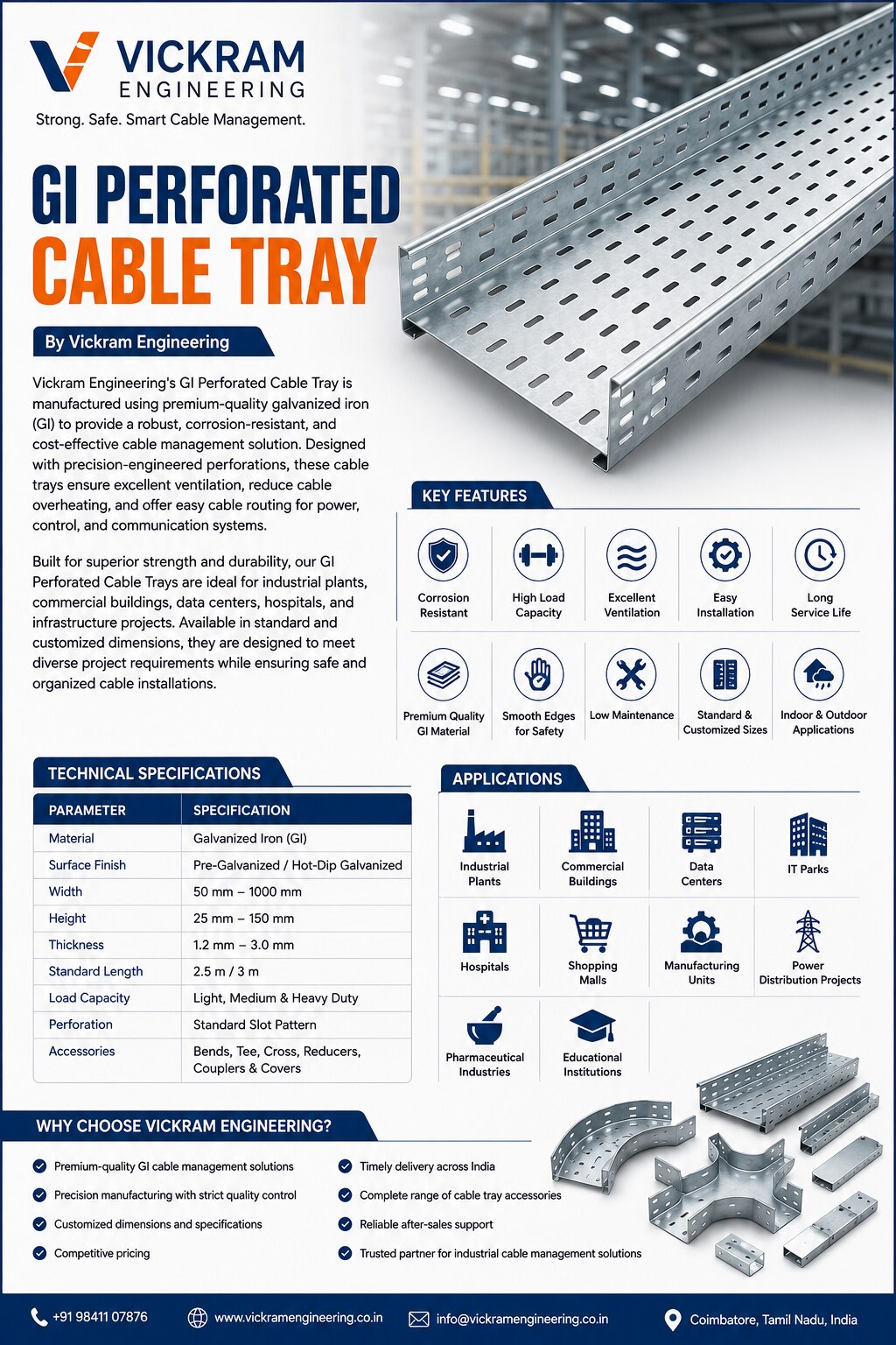 | GI Perforated Cable Tray Vickram Engineering's GI Perforated Cable Tray is manufactured using premium-quality galvanized iron (GI) to provide a robust, corrosion-resistant,... View product → |
 | Ladder Type Cable Tray Product Description Vickram Engineering is a leading manufacturer and supplier of premium-quality Ladder Type Cable Trays designed for supporting and... View product → |