A slotted C channel is only as suitable as its measured profile, connection hardware, load data, and corrosion specification. By the end, you will be able to compare manufacturers using project loads, support geometry, coating requirements, inspection documents, and an auditable submittal package rather than a catalogue label alone.
Key takeaways
- Confirm the channel profile, slot pattern, steel grade, and dimensions before comparing suppliers.
- Calculate point loads, spans, deflection, and safety factors for the complete support assembly.
- Select galvanizing, plating, or stainless steel for the actual corrosion environment.
- Request test reports, coating records, drawings, and traceability documents before project approval.
Identify the Channel Before You Compare Manufacturers
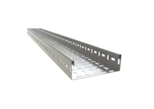
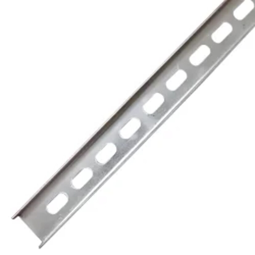
A useful slotted C channel definition is a cold-formed, C-shaped metal section with inward lips and a continuous slot pattern through its web. The slots accept compatible spring nuts, channel nuts, bolts, and threaded fittings without drilling. An un slotted C channel has the same general profile but needs drilled holes, clamps, or welded attachments.
Specify the complete profile, not “1-5/8-inch strut.” Include:
- Outside width and depth, lip geometry, base-metal thickness, steel grade, and minimum yield strength
- Slot length, width, shape, and pitch
- Coating process and finish, such as pre-galvanized steel or hot-dip galvanizing after fabrication
- Compatible nut, bolt, washer, splice, and bracket dimensions
- Design load table for that exact slotted profile, including span, support condition, load position, allowable deflection, and connection limits
| Option | What it means | What changes in selection |
|---|---|---|
| Slotted C channel | C-section with factory slots in the web | Check reduced section properties, slot-edge tear-out, and compatible hardware |
| Un slotted C channel | C-section without factory slots | Drilling or separate clamps alter installation and connection capacity |
| Strut channel | Broad product family, including Unistrut-style channels | Confirm actual dimensions, slot pattern, nuts, and manufacturer data |
| Angle iron or fabricated bracket | Open angle or formed assembly, not a channel | Do not substitute its load or connection data for channel data |
A strut channel comparison is valid only when geometry, material, span, loading, deflection limit, and safety factors match. Slots reduce net area and can change buckling and tear-out resistance, so never use solid-channel capacity for a slotted profile.
Size the Channel for the Actual Support Load
A channel is adequate only when its load capacity, connection capacity, and deflection all pass for the actual span and support arrangement. Start with the load per support: include tray weight, cable fill, fittings, covers, attached hardware, and specified wind or seismic actions, then apply the project’s required safety or resistance factor.
Use this sizing check:
- Determine support spacing and span between supports, including any cantilever beyond the last support.
- Select channel depth and width, steel thickness, steel grade, and section properties that resist the resulting bending and shear.
- Check the load position: a centred uniform tray load produces a different demand from a point load at one bracket or an eccentric load on one channel lip.
- Check slot dimensions and pitch for net-section loss, slot-edge tear-out, nut engagement, and the actual bracket connection.
- Confirm calculated deflection stays within the project limit; a channel that does not collapse can still sag enough to damage tray joints or misalign cables.
Compare manufacturer load tables only when span condition, support condition, channel orientation, load position, load type, deflection limit, and safety factors match. A simply supported uniform-load rating cannot validate a point-load or continuous-span installation.
Check the connection separately: bolt and washer size, permitted torque, splice-slip resistance, and cantilever strength can govern before the channel beam capacity. In a seismic installation, gravity ratings are insufficient; verify bracing, anchors, component restraint, and attachment design under the adopted building code and ASCE 7.
Match the Finish to the Corrosion Environment
Choose the finish from the wettest exposure and the damage the channel will receive, not from a generic “galvanized” label.
| Option | What it means | When it applies |
|---|---|---|
| Pre-galvanized C channel | Zinc-coated sheet is formed and slotted after coating; cut edges and welds need attention. | Dry indoor rooms, clean plant areas, and protected service spaces with limited moisture. |
| Hot-dip galvanized | The completed fabrication is immersed in molten zinc, coating edges and weld zones more completely. | Outdoor supports, washdown areas, humid plants, and industrial atmospheres. Specify vent and drain holes, and allow for dimensional tolerances. |
| Electro-galvanized | A thinner, electrically deposited zinc coating provides a smooth finish but limited sacrificial protection. | Dry interiors where appearance and light corrosion resistance matter; avoid persistent condensation or chemical exposure. |
| Stainless-steel channel | 304 suits many general environments; 316 performs better with chlorides because it contains molybdenum. | Coastal sites, salt spray, chemical areas, or frequent washdown. Neither grade is immune to pitting or crevice corrosion. |
| Painted channel | A barrier coating separates steel from the environment and requires intact coverage. | Dry, controlled interiors or projects requiring a specified colour. Repair scratches and exposed cut edges promptly. |
Ask for the ASTM A653 coating designation, such as G90, and the inspection basis; G90 states zinc mass on both sides, not thickness on one face. For hot-dip galvanized repairs after cutting or drilling, require an ASTM A780 procedure naming surface preparation, repair material, application method, and repaired thickness.
Separate galvanized steel from stainless steel, aluminium, or copper with compatible hardware, isolation washers, sealant, and drainage. Do not assume a painted channel provides electrical continuity or grounding; verify bonding hardware against the adopted electrical code.
Check Hardware, Connections, and Installation Conditions
Compatibility fails at the connection before the channel reaches its published beam capacity. Confirm that the proposed brackets, spring nuts, bolts, hex nuts and washers, threaded rod, anchors, bonding hardware, and seismic restraints match the channel’s actual geometry and the installation substrate.
- Record the slot dimensions and pitch, channel lip shape, steel thickness, and nut type; a 1-5/8-inch nominal width does not guarantee accessory compatibility.
- Check spring-nut engagement, bolt diameter, washer outside diameter, thread length, and the manufacturer’s permitted torque range. An oversized washer can interfere with the lips, while insufficient thread engagement can strip the connection.
- Verify slot-edge tear-out, cantilever connection strength, splice-slip resistance, and bracket capacity instead of relying only on the channel’s uniform-load table.
- Confirm anchor type, embedment depth, edge distance, base-material strength, and hole clearance for concrete, steel, or masonry attachments.
- Treat the channel as non-bonded unless the adopted electrical code and equipment listing accept it. Specify bonding jumpers, serrated washers, bonding fittings, or a separate grounding conductor, and remove or bridge coatings where the approved detail requires metal-to-metal continuity.
- For seismic work, obtain component restraint loads, brace spacing, anchor design, ductility requirements, and attachment verification under the project’s adopted code and ASCE 7. “Heavy duty” is not seismic qualification.
Request installation drawings showing every connection, splice, restraint, and torque value. A compatible channel system is one that can be assembled, bonded, anchored, and inspected without improvised hardware.
Demand Evidence You Can Use for Project Approval
A catalogue load number is not an approval value unless you can see its boundary conditions. Request a signed submittal showing channel geometry, steel thickness, section properties, orientation, span, support condition, load position, allowable deflection, and safety or resistance factors.
- Demand drawings that identify slots, splice plates, brackets, hole locations, connection capacities, installation torque limits, and any required bonding hardware.
- Request material certificates identifying grade, thickness, heat or batch number, and compliance with ASTM A653 where pre-galvanized sheet is specified.
- Request coating records: zinc designation and inspection basis for galvanized steel; repair procedure for cut or drilled areas under ASTM A780; and paint system, surface preparation, dry-film thickness, and exposure classification under ISO 12944.
- Ask for test reports or engineering calculations supporting load tables, seismic restraints, anchor design, brace spacing, and attachment verification under the adopted code and ASCE 7. “Heavy duty” is not seismic qualification.
- Require inspection records for dimensional checks, coating thickness, welds, torque verification, and repaired surfaces.
| Evidence | What it proves | Catalogue-only warning |
|---|---|---|
| Load table with conditions | A usable design capacity | One unexplained kN or kg figure |
| Connection and splice details | The assembly transfers load | Channel rating without joint capacity |
| Material and coating certificates | Supplied steel and finish are traceable | “Galvanized” with no ASTM A653 designation |
| Test report or calculation basis | The claim is auditable | “Tested” without method or report |
Ask Vickram Engineering for this complete evidence package before approval, then check that the submitted channel matches the dimensions installed.
Frequently asked questions
How do you identify the correct slotted C channel before comparing manufacturers?
Check the C-shaped profile, inward lips, web slot pattern, dimensions, material grade, and slot compatibility with spring nuts and fittings.
How do you size slotted C channel for an electrical support load?
Calculate cable, tray, conduit, and accessory loads across the actual span, then check point loads, deflection, connection strength, and safety factors.
Which finish should you choose for a slotted C channel?
Match the finish to exposure: zinc plating for dry interiors, hot-dip galvanizing for outdoor or damp areas, and stainless steel for severe chemical or salt exposure.
What evidence should a slotted C channel manufacturer provide?
Request dimensional drawings, material certificates, coating or galvanizing records, load data, inspection reports, batch traceability, and installation guidance.