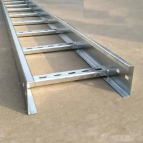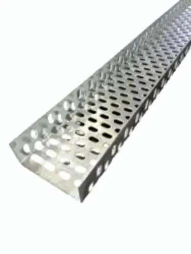
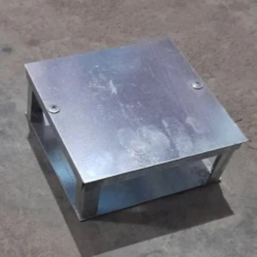
A tray route fails when the straight sections arrive without the bends, supports, couplers, bonding links or covers needed to complete the installation. By the end, you will be able to survey a route, specify compatible components, check load and electrical requirements, and evaluate whether a manufacturer can deliver a complete, installable system.
Key takeaways
- Survey cable quantities, diameters, weights, bend radii and separation requirements first.
- Order trays, fittings, covers and materials as one compatible system.
- Check load capacity, support spacing, bonding and installation details before approval.
- Require traceable drawings, schedules and documentation for the complete package.
Map the complete route before you order a single tray
A route survey becomes a complete cable management installation only when it records cables, geometry and supports—not just tray length. Start with cable quantity, outside diameter, mass, minimum bend radius and separation between power, control, instrumentation, data and fire-alarm circuits.
1. Perform a cable fill calculation using usable interior width, permitted fill, heat dissipation, pulling access and future spare capacity. Nominal tray width is not usable width. Record ceiling heights, wall offsets, building joints, seismic zones, fire-rated penetrations and maintenance access.
2. Mark every horizontal turn, vertical rise and drop, tee, cross, reducer, end cap, cover transition, penetration and access point on the drawing. Add straight tray, bends, tees, crosses, reducers, couplers, splice plates, covers, drop-out fittings, support brackets, trapeze arms, threaded rods, clamps, bolts, nuts, hold-downs and earthing links to the bill of materials.
3. Count every joint and support because missing splice hardware and support fittings increase installation labour and delay cable pulling. Request a layout take-off that identifies tray type and finish, fitting quantities, support spacing, splice hardware, cover type, bonding provisions and field-cut treatment.
Check each cable tray accessories schedule against the largest cable’s bend radius and required circuit separation. Ask the supplier to show firestop locations separately; a tray fitting does not qualify a fire-rated penetration. A quotation listing straight tray alone is incomplete.
Match tray, fittings, covers and materials as one compatible system
A fitting can bolt on and still fail if its inside radius damages the cable’s required bend. Specify tray type, width, side-rail height, rung or perforation pattern, finish and fitting geometry as one system.
For every bend, request the angle, inside radius, outside radius, straight tangent length, width and side-rail height; compare the inside radius with the largest cable manufacturer’s minimum bend radius, especially for medium-voltage, instrumentation and fibre-optic cables.
Check the purchase schedule for matching:
- Couplers, splice plates, covers, clamps and support hardware for the exact ladder, perforated or raceway profile
- Cover seating, clamp engagement and bolt-hole alignment, not just apparent dimensional fit
- Mild steel, galvanized steel, hot-dip galvanized steel or aluminium selected for indoor exposure, salt spray, chemicals, standing water, temperature and weight limits
- Galvanic separation where aluminium touches galvanized or mild steel, with cut edges treated using the approved repair coating
| Tray or raceway type | Functional advantage | Check before selection |
|---|---|---|
| Ladder tray | Ventilation and access for heavy cables | Cable restraint, bend fittings and falling-object exposure |
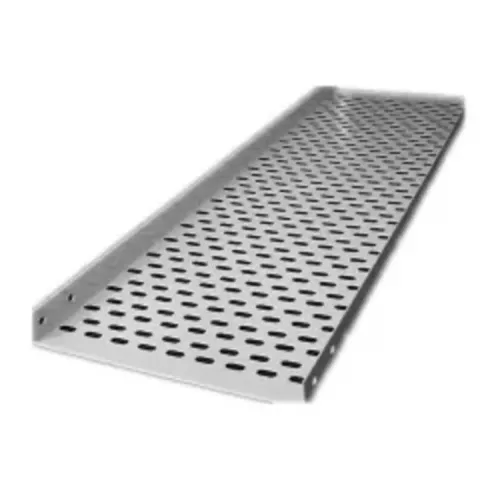
| Perforated tray | General support and flexible fixing | Hole pattern, fixing hardware and heat dissipation |
| Solid-bottom raceway | Dust and small-object protection | Heat retention, drainage and inspection access |
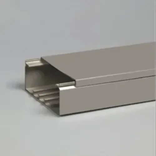
| Covered raceway | Enclosed routing; covered raceway compatibility | A solid cover protects against falling objects, dripping liquid and ultraviolet exposure but adds heat retention and wind load |
Verify load capacity, support design and installation details
A completed tray route is safe only when its weakest support and connection carry the calculated load at the actual support span—not when the tray load rating looks high in a catalogue.
Add cable mass, tray self-weight, cover weight, concentrated loads and environmental loads, then compare the total with the manufacturer’s load/span table for the selected tray, fitting geometry and installation orientation.
- Check trapeze arms, cantilever brackets, wall brackets, threaded rods, clamps, anchors and building attachment points for the combined load, including the required deflection limit and cantilever length.
- Add closer supports at elbows, tees, reducers, vertical transitions and concentrated cable entries when the manufacturer’s instructions require them.
- Position splice plates as specified; do not put a joint at an unsupported or heavily loaded location. Tighten bolts in the stated orientation so the plates transfer load as designed.
- Use the manufacturer’s sliding splice arrangement at an expansion joint. A rigid connection can restrain movement and damage the route or its building attachments.
- Set support spacing, building-joint movement and seismic restraint from the project design. Ordinary tray supports do not demonstrate seismic compliance; seismic regions require designed lateral and longitudinal restraints with qualified anchors.
- Remove burrs after cutting or drilling, repair damaged galvanizing or paint with the approved method, and face fastener heads away from cable jackets.
Record the selected load/span table, support calculations, anchor details and inspection results with the installation drawings. A tray can meet its longitudinal capacity and still fail because a bracket, anchor or building connection is underdesigned.
Route cables for separation, bending, bonding and future maintenance
Complete the route after the metalwork is fixed by controlling cable separation, bend clearance, electrical continuity and future access—not by pulling cables into any space that fits.
1. Separate power, control, instrumentation, communications and fire-alarm circuits according to the project specification, governing electrical code and equipment manufacturer’s electromagnetic-compatibility requirements. Use separate trays or specified barriers when unlike circuits cannot share a route. Cross them at 90 degrees where the design permits.
2. Check every bend, tee, rise, drop and entry against the largest cable’s minimum bend radius. A tray width does not prove bend clearance. Install vertical retainers so cables cannot slide onto sharp edges, and keep penetrations compatible with their separately qualified firestop systems.
3. Complete tray bonding and connect the metalwork to the project earthing system as required by the code and project standard. Metallic tray may serve as an equipment grounding conductor only when its listing or design permits it. Add bonding jumpers across expansion joints, removable sections, painted interfaces and other discontinuities.
Record an earthing continuity test; tight bolts alone do not prove a bond.
4. Inspect alignment, cover fit, cable fill, bend-radius clearance, support spacing, burrs, coating damage and missing fasteners before pulling cables. Correct defects while access remains open.
5. Issue as-built drawings showing tray sizes, fittings, supports, penetrations, bonding points and spare capacity. Leave room to remove covers, add cables, inspect corrosion and fasteners, and replace damaged fittings without dismantling the route.
Assess the manufacturer’s ability to supply a complete, traceable package
Approve the supplier only after the submittal proves that every tray section and accessory belongs to one coordinated system. Ask for dimensional drawings showing standard widths, side-rail heights, fitting radii, tolerances, finish options, and field-cut repair instructions.
Require load/span tables for the selected tray, fitting geometry and support spacing, plus material certificates, coating thickness records, inspection reports and IEC 61537 classification or test evidence when the project requires it.
- Request a coordinated take-off covering tray, bends, tees, crosses, reducers, couplers, splice plates, covers, supports, fasteners and bonding jumpers. Obtain written confirmation that widths, rail heights, hole patterns, bolt sets, covers and bonding provisions are compatible.
- Require sample approval for nonstandard fittings. Confirm that the manufacturer can fabricate each unusual bend without imposing a field-made radius that reduces cable clearance, breaks load continuity or leaves corrosion-prone cut edges.
- Check batch traceability from material certificates through inspection records. Ask how the supplier records galvanizing or coating thickness and how damaged finishes, drilled holes and cut edges are repaired on site.
- Confirm packaging and delivery coordination so splice plates, covers, bolts, clamps and bonding jumpers do not arrive after the tray. Installation advice helps when route dimensions change; it does not replace approved drawings or an engineered load check.
For a Bengaluru project, evaluate Vickram Engineering by its coordinated accessory take-off, custom fabrication evidence and traceable batches, not by a broad supply claim. List every component, document and inspection hold point in the purchase order.
Related products
 | Ladder Type Cable Tray Product Description Vickram Engineering is a leading manufacturer and supplier of premium-quality Ladder Type Cable Trays designed for supporting and... View product → |
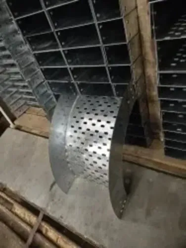
Horizontal Cable Tray Bend Vickram Engineering's Horizontal Cable Tray Bend is a precision-engineered cable management accessory designed to facilitate smooth directional... View product → |
Frequently asked questions
What should you record before ordering cable trays?
Record cable quantity, outside diameter, mass, minimum bend radius, route geometry, supports and separation between power, control, instrumentation, data and fire-alarm circuits.
How do you choose compatible cable tray accessories?
Match the tray, fittings, covers, connectors, supports and material finish as one system, then check that each component fits the route and installation requirements.
What load and support details must you verify?
Verify the combined cable load, tray capacity, support design, support spacing, fixing method, bonding arrangement and installation details.
How should cables be arranged inside the tray?
Route cables with the required separation, preserve their minimum bend radius, provide bonding continuity and leave access for inspection, additions and maintenance.
Related products
 | Galvanized Cable Tray Vickram Engineering's Galvanized Cable Tray is engineered to provide a strong, reliable, and corrosion-resistant cable support system for industrial,... View product → |
Cable Trays The GI Bolt Nut Type Cable Tray is a robust and dependable cable management solution designed for safe routing and support of electrical,... View product → |
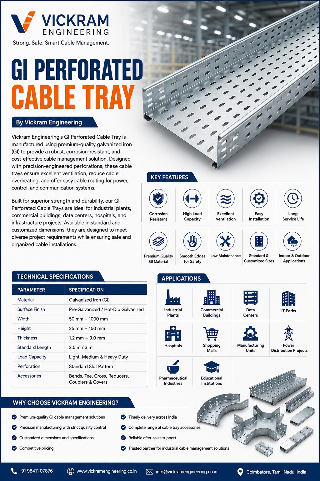 | GI Perforated Cable Tray Vickram Engineering's GI Perforated Cable Tray is manufactured using premium-quality galvanized iron (GI) to provide a robust, corrosion-resistant,... View product → |
 | Cable Raceway Systems The GI Raceway with Cover is a premium cable management solution designed to provide complete protection and organized routing of electrical,... View product → |